🌐 Session 4 — Connecting Two Routers via Serial Interface
🕛 Overview
In this session, we expanded our Packet Tracer lab by connecting two separate LAN-based networks, each with its own router. The goal was to enable inter-router communication using Serial interfaces, demonstrating a key concept in WAN connectivity.
This setup illustrated how data travels between multiple networks through routers interconnected by a point-to-point serial link, introducing concepts such as DCE/DTE roles, clock rate configuration, and static routing fundamentals.
🔍 Concept Recap:
- DCE (Data Communications Equipment) — provides the clock signal for synchronization on the serial link. In Packet Tracer, one side of the serial cable is automatically designated as DCE.
- DTE (Data Terminal Equipment) — receives the clock signal from the DCE and adjusts its transmission timing.
- Clock Rate — determines how fast bits are transmitted over the serial link and must be configured on the DCE side using the
clock ratecommand.- Static Routing Fundamentals — defines explicit paths between networks. While not fully configured in this session, we discussed how routers use routing tables to forward packets between subnets.
🧩 Part 1 — Network Topology Overview
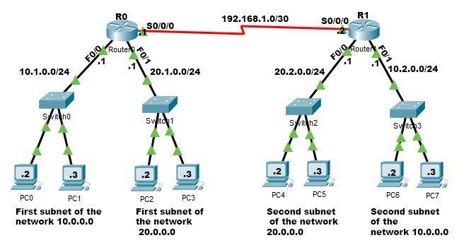
We built a network with two main routers (R0 and R1) interconnected via a Serial link. Each router connects to two separate LANs through FastEthernet interfaces.
🖊️ Addressing Summary
| Network | Router | Interface | IP Address | Subnet Mask | Description |
|---|---|---|---|---|---|
| 10.1.0.0/24 | R0 | Fa0/0 | 10.1.0.1 | 255.255.255.0 | First subnet of network 10.0.0.0 (Switch0, PCs) |
| 20.1.0.0/24 | R0 | Fa0/1 | 20.1.0.1 | 255.255.255.0 | First subnet of network 20.0.0.0 (Switch1, PCs) |
| 20.2.0.0/24 | R1 | Fa0/0 | 20.2.0.1 | 255.255.255.0 | Second subnet of network 20.0.0.0 (Switch2, PCs) |
| 10.2.0.0/24 | R1 | Fa0/1 | 10.2.0.1 | 255.255.255.0 | Second subnet of network 10.0.0.0 (Switch3, PCs) |
| 192.168.1.0/30 | R0 | S0/0/0 | 192.168.1.1 | 255.255.255.252 | Serial link to R1 (DCE side) |
| 192.168.1.0/30 | R1 | S0/0/0 | 192.168.1.2 | 255.255.255.252 | Serial link to R0 (DTE side) |
🗿 Explanation:
- Each LAN is assigned a unique subnet to avoid conflicts.
- Routers serve as default gateways for their connected PCs.
- The serial link (192.168.1.0/30) provides inter-router communication.
- R0 is the DCE side (it sets the clock rate), while R1 is the DTE side.
- A /30 subnet gives only 2 usable IPs, which is perfect for point-to-point links (like between two routers). Since the block size is 4, this subnet includes:
| Type | Address | Description |
|---|---|---|
| Network address | 192.168.1.0 | identifies the subnet |
| First usable host | 192.168.1.1 | device 1 |
| Second usable host | 192.168.1.2 | device 2 |
| Broadcast address | 192.168.1.3 | used to talk to all hosts in the subnet |
🔧 Part 2 — Serial Connection Setup
🔌 Serial Connection Explanation:
The serial cable connects R0 and R1 through their Serial0/0/0 interfaces. In Packet Tracer, you can identify the DCE side by hovering over the cable — a small label indicates which end is DCE. The DCE side (R0) must define the clock rate to synchronize communication. Without it, the link LEDs stay orange instead of green.
⚙️ Part 3 — Router Configuration (CLI)
🖥️ R0 Configuration (DCE)
Router(config)# interface Serial0/0/0
Router(config-if)# ip address 192.168.1.1 255.255.255.252
Router(config-if)# clock rate 19200
Router(config-if)# no shutdown
Router(config-if)# exit
🖥️ R1 Configuration (DTE)
Router(config)# interface Serial0/0/0
Router(config-if)# ip address 192.168.1.2 255.255.255.252
Router(config-if)# no shutdown
Router(config-if)# exit
🐟 Note: Only the DCE side (R0) sets a clock rate. Use
show controllers serialto check which router is DCE.
🔄 Part 4 — Verification and Testing
After configuring the routers, verify that the Serial and FastEthernet interfaces show green link lights.
From any PC in R0’s LAN (e.g., 10.1.0.2), test connectivity to a PC in R1’s LAN (e.g., 10.2.0.2):
ping 10.2.0.2
A successful ping confirms that inter-router serial communication and routing between subnets work correctly.
🧬 Part 5 — OSI Layer Perspective
| OSI Layer | Device/Function in this Lab | Example |
|---|---|---|
| Layer 1 — Physical | Serial Cable (DCE/DTE), Ethernet | Clock rate synchronization, cabling |
| Layer 2 — Data Link | Switches | Frame forwarding using MAC addresses |
| Layer 3 — Network | Routers | IP addressing, routing between subnets |
| Layer 4–7 | Not directly configured | Ping (ICMP) operates at Layer 3–4 |
💡 Insight: The serial link operates across both the Physical and Network layers, allowing routers to connect multiple LANs through WAN links.
📚 Concepts Reinforced
- Routers connect different networks via serial or Ethernet interfaces.
- DCE vs DTE: DCE provides clock rate timing.
- Clock Rate Command: Required only on the DCE side.
- Each LAN must have its own IP subnet.
no shutdownactivates router interfaces.pingverifies connectivity between devices.- Routers operate at OSI Layer 3, switches at Layer 2.
- Serial connections simulate WAN links for inter-router communication.
📝 Exam Tips
- Identify the DCE side before setting
clock rate. - Each router interface must be on a different subnet.
-
If Serial LED is orange, check:
no shutdownstatus- Clock rate configuration (on DCE)
- Use
show ip interface briefto confirm status and addressing. - Use
pingfor end-to-end connectivity tests. - Remember: Routers → Layer 3, Switches → Layer 2.
- Clock rate applies only to serial links, not Ethernet.
🏁 Summary
In Session 4, we:
- Expanded our setup to include two routers (R0 and R1).
- Configured four LANs using different subnets.
- Established a Serial connection between routers (192.168.1.0/30).
- Assigned IPs and set the clock rate on the DCE side (R0).
- Verified connectivity using ping across networks.
- Reinforced concepts of WAN links, routing, and DCE/DTE synchronization.
🗿 This session bridges LAN fundamentals with WAN concepts, demonstrating inter-router communication over a serial connection.