Lesson 6 – Data Link Layer (Layer 2)
Summary
In Lesson 6, we officially moved up from the Physical Layer (Layer 1), which covered the first five lessons, into the Data Link Layer (Layer 2). The professor illustrated the transition using a multi‑LAN diagram containing computers → switches → routers, and explained how message units grow in complexity as we move up the OSI model.
Part A — Transition From Layer 1 to Layer 2
A quick look at: VLANs and Inter-VLAN Routing
- VLAN (Virtual LAN): Logically divides one physical switch into multiple isolated LANs.
- Inter-VLAN Routing: Allows communication between VLANs using a router or Layer 3 switch.
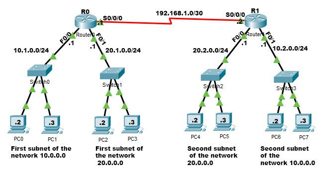
- Computers connected to switches → representing the Physical Layer.
- Switches connected to routers → representing the Data Link Layer.
- Routers connected to each other → representing the Network Layer.
The following conceptual hierarchy exists:
| OSI Layer | Device Example | Data Unit Name |
|---|---|---|
| Layer 1 – Physical | Cables, NICs, bit-level transmission | Cell / bit stream |
| Layer 2 – Data Link | Switches | Frame |
| Layer 3 – Network | Routers | Packet |
📌 Increasing Data Abstraction
As we move upward in the OSI model:
- The size of the message unit increases.
- More metadata (headers, control fields) is added.
- Each layer encapsulates the lower one.
This is why a cell becomes a frame, which later becomes a packet.
Layer 2 — Switching / Data Link Layer
Layer 2 is responsible for node‑to‑node delivery. It ensures that the physical layer’s raw bits are grouped, structured, and reliable enough for the network layer.
⭐ Key Device: Switches
Switches operate using store-and-forward switching:
- The switch receives the entire frame.
- It stores it temporarily.
- It checks it (including error detection).
- It forwards it to the correct outgoing port.
This behavior contrasts with routers (Layer 3), which make forwarding decisions based on IP headers.
Responsibilities of Layer 2
1. Framing
📘 Message → Cells (Framing Breakdown Diagram)
graph LR
    A[Header + Message] --> B[Header + C1]
    A --> C[Header + C2]
    A --> D[Header + C3]
    A --> E[Header + C4]
Each cell carries the same original frame header, while the message is segmented into smaller parts.
Framing means taking a stream of bits from Layer 1 and grouping them into structured, identifiable units called frames.
Why Do We Need Frames?
Layer 1 sends raw bits with no boundaries. Layer 2 must answer:
“Where does the message start, and where does it end?”
To do that, each frame contains:
- Start indicators
- End indicators
- A header (addressing information)
- The payload
- Possibly a trailer (error detection)
📌 Layer Responsibilities
Each layer checks the layer below it and prepares data for the layer above it.
When a message moves down the layers:
- It becomes more fragmented.
- Each fragment receives its own headers.
Example:
- A message at Layer 3 (packet) descends to Layer 2 → becomes frames.
- Each frame descends to Layer 1 → becomes cells/bitstreams.
Frame Boundary Detection
The receiver must know:
“These bits belong to the frame; these other bits do not.”
We where given the “beep before and after” analogy — meaning the sender marks boundaries.
One way to achieve this is Character Stuffing.
1. Character Stuffing / Byte Stuffing
Example using the character A as a delimiter:
- Add
Aat the start and end of the frame. - If
Aappears inside the actual data, replace it withAA.
The receiver scans forward:
- A single A marks a boundary → removed.
- A double AA becomes a single
Ainside the message.
Result
- The real message stays intact.
- The boundaries are perfectly clear.
2. Bit Stuffing (Brief Overview)
Used when the protocol uses bit patterns instead of characters. For example, HDLC uses the pattern:
01111110 (flag)
Whenever the sender sees five consecutive 1s inside the data, it inserts a 0. The receiver removes these inserted 0s.
This prevents accidental appearance of the flag pattern inside the message.
Other Framing Methods (Brief Mentions)
- Flag-based framing: Uses special flag bytes to mark frame boundaries.
- Byte Stuffing: Escapes reserved characters inside the payload.
- Bit Stuffing: Inserts bits to prevent accidental flag patterns.
- Length-based framing: A header field defines total frame size.
- Clock-based methods (e.g., Manchester): Ensure timing synchronization at Layer 1 but indirectly help maintain frame boundaries at Layer 2.
2. Error Control (Introduction)
Layer 2 provides:
- Error Detection – identifying that something is wrong.
- Error Correction – locating and fixing the error.
Error Detection Examples
- Parity bits
- Checksums
- CRC (Cyclic Redundancy Check) — used in Ethernet frames
Error Correction Examples
- Hamming codes
(📌 Note: Full error‑control mechanisms such as parity, checksum, CRC, and Hamming will be discussed in Lesson 7.)
Switch Behavior — Flat vs. Intelligent Forwarding
Switches are originally flat devices, meaning:
- They flood frames out to all ports except the one they arrived on.
- They do not initially know which MAC address belongs to which port.
Over time, switches build a MAC Address Table and become smarter.
Lesson Summary
- We moved from Layer 1 → Layer 2 and examined how data grows in structure.
- We learned how framing creates boundaries using character stuffing, bit stuffing, and other methods.
- We introduced error detection and correction, which will be expanded in Lesson 7.
- We saw how switches behave and how VLANs logically segment a LAN.